
Choosing the right High Frequency AC/DC Rectifiers in 2026 requires more than comparing power ratings. Buyers must examine efficiency, switching frequency, output stability, thermal performance, and service support. A compact rectifier may look attractive on paper, yet struggle inside a dusty factory cabinet or a poorly ventilated charging station.
This guide introduces leading rectifier options for industrial power supplies, telecommunications, battery charging, renewable energy systems, and specialized equipment. It focuses on practical buying details, including input voltage range, power factor correction, ripple control, protection functions, cooling methods, and digital monitoring. These details affect operating costs and maintenance schedules. They also influence system safety.
Small details matter.
Experienced procurement teams usually request test reports, efficiency curves, warranty terms, and evidence of compliance with applicable standards. They also confirm performance at partial load, because real systems rarely operate at full capacity all day. A supplier’s laboratory data is useful, but field references can reveal noise, heat, software limits, or delayed support.
There is no universal best model. A high-frequency unit designed for telecom backup may not suit a demanding industrial motor system. Buyers should match the rectifier with the complete power architecture, including transformers, batteries, controls, and downstream loads. Installation conditions deserve equal attention. Ambient temperature, airflow, humidity, and cabinet space can change expected performance.
Some product claims may appear overly confident.
This 2026 overview helps buyers compare technologies with a more balanced approach. It highlights strong candidates while recognizing trade-offs, unavailable data, and the need for independent verification. A careful decision begins with measurable requirements, not attractive marketing language.
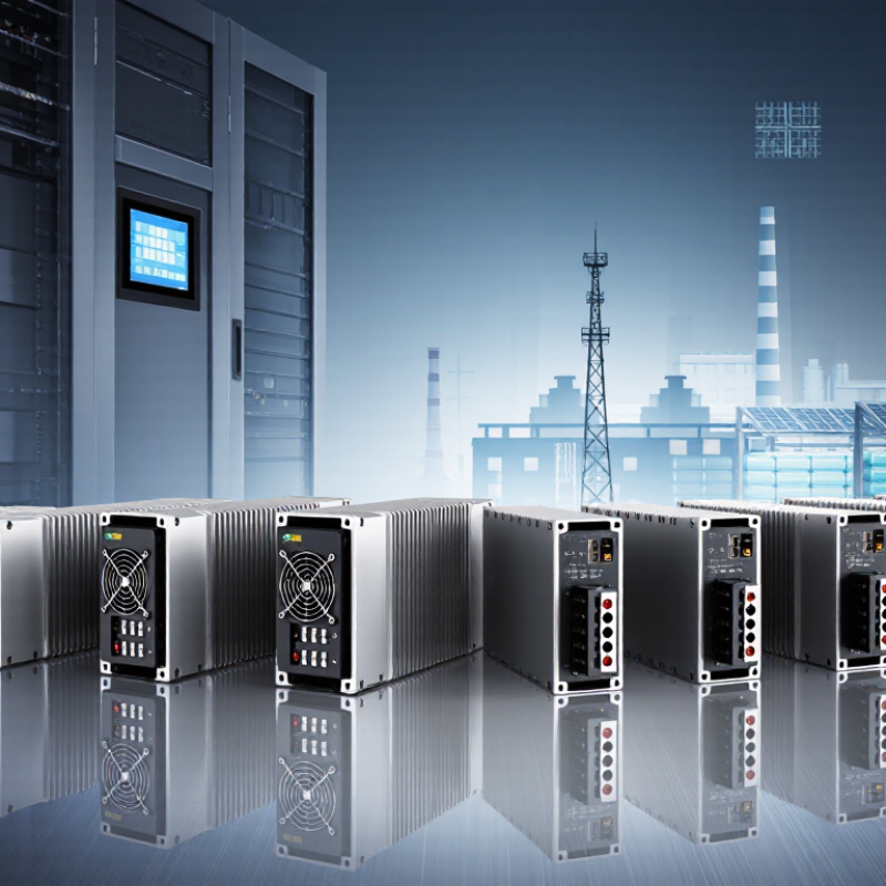
A high-frequency AC-DC rectifier converts alternating input power into regulated direct current while operating far above the 50/60 Hz line frequency. In a typical design, an input filter reduces electrical noise, and a bridge rectifier produces a pulsating DC bus. Power switches then chop this voltage at tens or hundreds of kilohertz.
This is the key idea.
The switching waveform passes through a high-frequency transformer when isolation is required. The transformer can be smaller than a traditional low-frequency unit, which helps reduce weight and enclosure size.
On the output side, diodes or synchronous switches rectify the waveform again. An inductor and capacitor then smooth the current into usable DC. Feedback circuits constantly compare output voltage with a reference and adjust switching timing.
Small timing errors matter.
For buyers, practical evaluation should include input range, output current, ripple, efficiency, isolation rating, cooling method, and protection against overvoltage or short circuits.
Thermal testing under continuous load is essential; a unit that performs well for ten minutes may struggle after several hours. I have found that published efficiency figures can look impressive, yet depend on ideal voltage and temperature.
That deserves careful questioning.
High-frequency operation also creates electromagnetic interference, so layout, shielding, grounding, and compliance testing cannot be treated as minor details. A quiet prototype may become noisy inside a metal cabinet.Winvalid
In 2026, buyers should compare AC/DC rectifiers beyond headline efficiency. The IEA Electricity 2024 report expects data-center electricity use to exceed 1,000 TWh by 2026. That pressure makes every conversion loss important. Check efficiency at 10%, 50%, and full load, not only the peak value. Record switching frequency, power density, input range, power factor, and total harmonic distortion. A 98% rating may look excellent, yet poor light-load performance can increase annual energy waste.
Thermal behavior deserves equal attention. Compare continuous output power, derating curves, cooling requirements, and measured case temperature. Ask for ripple voltage, transient response, hold-up time, isolation voltage, and conducted-emissions test results. The Uptime Institute’s 2024 Global Data Center Survey reported an average PUE of 1.56, showing that conversion equipment affects wider facility efficiency. Higher frequency can reduce magnetics size, but it may increase EMI and switching losses. I have seen compact designs become difficult to cool. The specification sheet rarely tells that story.
Tips: Request test data at your real voltage and load profile. Verify efficiency after warm-up, not only at room temperature. Check whether protection functions reset safely after overloads. Compare service life, fan behavior, and component temperature limits. Do not choose the highest frequency automatically. A slightly slower rectifier may deliver better reliability, lower noise, and easier maintenance. Some published figures remain incomplete, so buyers should challenge unclear test conditions.
High-frequency AC-DC rectifiers convert grid power into stable DC power for compact equipment. Common types include diode bridges, active PFC rectifiers, Vienna rectifiers, and bridgeless totem-pole designs. Diode bridges remain simple and affordable, but they create higher conduction losses. Active PFC improves power factor and reduces input current distortion. Vienna rectifiers suit three-phase systems, especially industrial drives and high-power chargers. Totem-pole rectifiers offer lower losses at high switching frequencies, though control design becomes less forgiving.
Applications are expanding in data centers, electric-vehicle charging stations, telecom systems, and renewable-energy inverters. The IEA Electricity 2024 report estimates that data centers consumed about 460 TWh globally in 2022. Demand may exceed 1,000 TWh by 2026.
Efficient front-end rectifiers can reduce heat inside dense power shelves. That matters when airflow is limited. The U.S. Department of Energy’s 2024 data-center report estimates American data-center consumption could reach 325–580 TWh by 2028. Efficiency is no longer a minor specification.
Buyers should compare switching frequency, power factor, total harmonic distortion, thermal limits, and serviceability. Silicon carbide and gallium nitride devices can support faster switching and smaller magnetics. However, higher frequency can increase electromagnetic interference and gate-drive complexity. The trade-off is real. A rectifier with impressive laboratory efficiency may underperform in dusty rooms or unstable grids. I would request full-load efficiency curves, not one headline number. Noise still matters. Thermal testing under actual load remains essential.
When buyers compare high frequency AC DC rectifiers in 2026, safety should guide the first inspection. Check insulation systems, protective earthing, creepage, clearance, and accessible surface temperatures. High switching frequencies can reduce transformer size, but they may increase electromagnetic interference and switching stress. During evaluation, use thermal imaging, oscilloscope measurements, and leakage-current tests under realistic loads. I prefer testing at low, typical, and peak input conditions. A perfect datasheet is not enough.
Efficiency depends on the complete operating profile, not one impressive percentage. Measure conversion efficiency at standby, half load, and full load. Review power factor, harmonic current, cooling demand, and transient response. A rectifier may perform efficiently at full load but waste energy during long periods of light operation. That matters in control cabinets and continuously powered equipment. Small losses become heat.
Compliance requires evidence that matches the intended market and installation environment. Request current test reports, material declarations, EMC results, and safety certification documents. Check whether evaluations address conducted emissions, radiated emissions, surge, electrostatic discharge, and abnormal operating conditions. Requirements can differ by region, application, and final equipment category. Treat copied certificates carefully. I have seen documents with valid laboratory names but unsuitable product variants. One practical weakness remains: buyers sometimes trust labels more than test conditions. Review the details, question unclear assumptions, and record every acceptance limit before purchasing.
| Rectifier Category | Typical Switching Frequency | Typical Output Power | Typical Output Voltage | Typical Peak Efficiency | Power Factor | Electrical Isolation | Main Advantages | Key Limitations | Safety and Compliance Factors | Best-Fit Applications |
|---|---|---|---|---|---|---|---|---|---|---|
| High-Frequency Diode Bridge Rectifier | 20–150 kHz | 50 W–3 kW | 12–400 VDC | 85–93% | 0.55–0.70 without PFC | Usually provided by a high-frequency transformer | Simple design, low component count, fast development, and economical maintenance. | Higher switching and conduction losses; normally requires an additional power-factor-correction stage for regulated commercial equipment. | Verify creepage and clearance, transformer insulation, fuse coordination, over-temperature protection, and conducted-emission performance. | Industrial controls, auxiliary power supplies, chargers, and cost-sensitive embedded equipment. |
| Active PFC Boost Rectifier | 50–250 kHz | 300 W–5 kW | Typically 380–420 VDC intermediate bus | 94–98% | 0.95–0.99 at rated load | Not inherently isolated; isolation is normally added in the downstream converter | Low input-current distortion, high power factor, wide input-voltage capability, and improved compliance with harmonic-current limits. | Requires control circuitry, current sensing, inrush management, and careful electromagnetic-interference design. | Evaluate input over-voltage protection, brownout behavior, bulk-capacitor discharge, functional insulation, and harmonic-current requirements such as IEC 61000-3-2 where applicable. | Server power supplies, telecom rectifiers, industrial power converters, and energy-efficient AC-DC front ends. |
| Totem-Pole Bridgeless PFC Rectifier | 50–500 kHz | 1–10 kW | Typically 380–420 VDC intermediate bus | 96–99% | 0.98–0.999 at rated load | Not inherently isolated | Removes the conventional diode bridge, reducing conduction loss and enabling very high power density. | More complex gate-drive timing, common-mode-noise control, dead-time management, and light-load operation. | Check high-voltage switching-node insulation, shoot-through prevention, residual-current behavior, electromagnetic compatibility, and protective-earth design. | High-density data-center power, battery chargers, renewable-energy converters, and premium industrial power systems. |
| Vienna-Type Three-Phase Rectifier | 20–100 kHz | 5–30 kW | 650–800 VDC intermediate bus | 96–99% | 0.98–0.999 at rated load | Not inherently isolated | Three-phase operation, low input-current distortion, balanced current draw, and high power density. | Requires a three-phase input, neutral-point voltage control, coordinated gate driving, and more advanced protection. | Assess phase-loss protection, line-to-line surge protection, DC-bus over-voltage protection, touch-current limits, and enclosure requirements. | Fast EV chargers, industrial drives, high-power battery systems, and three-phase test equipment. |
| High-Frequency Isolated LLC Rectifier | 70–500 kHz | 300 W–10 kW | 24–800 VDC | 95–99% | Usually 0.95–0.99 with an upstream PFC stage | Yes, through a high-frequency transformer | Soft switching, low switching loss, low acoustic noise, and high efficiency near the designed operating point. | Regulation range can be narrower; transformer design and variable-load performance require careful optimization. | Verify reinforced insulation, transformer partial-discharge performance where relevant, output-voltage limits, insulation monitoring, and safe discharge of capacitors. | Telecom power, medical equipment, industrial automation, server supplies, and high-efficiency chargers. |
| Phase-Shifted Full-Bridge Rectifier | 50–250 kHz | 1–20 kW | 48–800 VDC | 94–98% | Usually 0.95–0.99 with an upstream PFC stage | Yes, through a high-frequency transformer | Suitable for high power, supports soft switching, and offers good transformer utilization and output regulation. | Circulating current and light-load efficiency can reduce overall performance; synchronous rectification may be needed at low output voltages. | Review transformer isolation, gate-drive interlocks, short-circuit response, leakage inductance, thermal margins, and conducted/radiated emissions. | Industrial DC supplies, telecom rectifier shelves, battery chargers, and high-power DC conversion. |
| Synchronous Rectifier Secondary Stage | 100 kHz–1 MHz | 50 W–3 kW | 5–120 VDC | Up to 97–99% in low-voltage designs | Determined by the upstream AC-DC front end | Usually paired with an isolated high-frequency transformer | Replaces secondary diodes with controlled switches, significantly reducing conduction loss at high output current and low voltage. | Requires accurate timing, reverse-current control, suitable MOSFET selection, and robust protection against cross-conduction. | Check safe gate-drive operation, drain-source voltage margin, thermal cycling, output short-circuit protection, and isolation barriers. | Low-voltage telecom supplies, USB-C power systems, battery chargers, and high-current embedded power modules. |
| Modular Three-Phase AC-DC Rectifier Module | 20–100 kHz | 10–50 kW per module | 400–800 VDC | 95–98% | 0.98–0.999 at rated load | Depends on the module architecture; many are non-isolated at the input stage | Scalable capacity, hot-swap options, current sharing, serviceability, and centralized monitoring. | System efficiency depends on load sharing, bypass design, cooling, control communication, and partial-load operation. | Evaluate module-to-module fault isolation, busbar clearances, protection coordination, airflow, EMC, and system-level emergency shutdown. | Telecom infrastructure, data centers, industrial battery banks, microgrids, and distributed power systems. |
| Bidirectional AC-DC Active Front End | 5–50 kHz | 5–100 kW | 400–1,000 VDC | 94–98% | 0.98–0.999 in rectification mode | Usually non-isolated at the grid interface | Supports controlled rectification, regenerative operation, adjustable reactive power, and energy flow in both directions. | Higher software, sensing, filtering, and protection complexity; requires careful grid synchronization. | Assess anti-islanding, grid-code compatibility, DC injection, leakage current, fault ride-through, surge protection, and emergency isolation. | Energy storage systems, regenerative drives, vehicle-to-grid equipment, microgrids, and industrial test systems. |
Evaluation note: The figures are representative engineering ranges for 2026 purchasing comparisons, not guaranteed product ratings. Actual performance depends on input voltage, load profile, switching devices, cooling method, control strategy, transformer design, power-factor-correction configuration, and certification conditions. Confirm the final design against applicable requirements, including IEC 62477-1, IEC 61010-1, IEC 62368-1, IEC 60601-1, IEC 61000-3-2, IEC 61000-6-x, UL 1557, UL 62368-1, or other standards relevant to the end application.
Choosing the right high-frequency AC DC rectifier starts with the system, not the catalog. Measure input voltage, frequency, load current, and permitted ripple under real operating conditions. A laboratory reading may differ from a motor cabinet on a hot afternoon. High-frequency operation can reduce transformer size. It can also increase switching loss and electromagnetic noise. That trade-off deserves numbers. Check peak current, inrush behavior, and duty cycle before comparing rated output.
Match the rectifier’s output to the downstream DC bus, battery charger, or control circuit. For a 48 V bus drawing 20 A, a 1 kW unit may be too close to its limit. Leave practical thermal headroom, especially inside a sealed enclosure. Review efficiency at 25%, 50%, and full load. The best figure at one point can hide poor performance elsewhere. Inspect cooling paths, fan failure response, insulation strength, and short-circuit protection. Request test reports, tolerance data, and production traceability. Claims without measurements are weak evidence.
Installation details often decide reliability. Keep high-current conductors short, use suitable terminals, and separate sensing wires from switching nodes. Verify emissions in the finished enclosure, not only on a bench. I have seen acceptable prototypes fail after cable routing changed. That mistake is easy to repeat. Also confirm service access, replacement time, and local safety requirements. A rectifier that fits electrically may still be wrong for maintenance, heat, or future load growth. Document assumptions before purchase, including ambient temperature and expected overload duration.
It converts grid electricity into stable direct current for compact equipment. Higher switching frequency can reduce transformer size. It may also increase heat and electromagnetic noise.
A diode-bridge rectifier is usually simple, reliable, and affordable. However, it creates higher conduction losses. Not always efficient.
Choose it when lower input distortion and improved power factor matter. It can reduce wasted current in demanding systems. Check performance across several load levels.
Three-phase rectifiers suit industrial drives and high-power charging equipment. They can handle substantial input power. Confirm the available voltage and phase arrangement first.
Compare switching frequency, efficiency, power factor, distortion, thermal limits, and serviceability. Request full-load efficiency curves, not one headline number. One figure can mislead.
Leave practical thermal headroom above the expected load. For a 48-volt bus drawing 20 amps, a 1-kilowatt unit may be too close to its limit. Sealed enclosures need extra caution.
Heat, dust, unstable grids, and restricted airflow can change performance significantly. Test at 25%, 50%, and full load. A cool laboratory bench is not enough.
Keep high-current cables short and use suitable terminals. Separate sensing wires from noisy switching nodes. Cable routing can turn an acceptable prototype into a failed installation. I would recheck it.
This guide to 2026’s top High Frequency AC/DC Rectifiers explains how these power-conversion devices transform alternating current into stable direct current while operating at higher switching frequencies for improved control, compact design, and reduced energy loss. It outlines the main specifications buyers should compare, including input and output voltage ranges, rated power, efficiency, switching frequency, ripple, power factor, thermal performance, protection features, and expected service life. It also reviews common rectifier types and their applications in industrial equipment, telecommunications, transportation systems, renewable energy installations, and other demanding power environments.
The article further highlights the importance of electrical safety, insulation, cooling, electromagnetic compatibility, and compliance with applicable regional standards. Buyers are encouraged to evaluate load behavior, operating conditions, installation space, maintenance requirements, expandability, and total ownership cost rather than focusing only on purchase price. By matching the rectifier’s electrical characteristics and protection capabilities with the system’s real operating needs, organizations can achieve reliable performance, efficient energy use, and safer long-term operation.