Next-Generation Three-Phase Resonant Converters: Technical Architecture, Industrial Procurement Strategies, and High-Density Power Benchmarks
Empowering heavy industry, railway traction systems, and megawatt energy storage with soft-switching zero-voltage topologies, planar magnetics integration, and ultra-low EMI profiles.
Discover how three-phase interleaved LLC and LCC resonant tanks suppress input/output ripple current by 80% while enabling sub-millisecond dynamic response across broad temperature ranges.
Tailored High-Power Solutions for Global Procurement Leads
From custom magnetic matrix synthesis to 20-year obsolescence management, Premium PSU delivers certifiable, mission-critical power conversion for global OEMs.
EN 50155 & EN 45545-2 Railway Fire/Smoke Compliance
Planar Magnetics with Integrated Resonant Leakage Control
Soft Switching (ZVS/ZCS) Efficiency Peak >97.8%
Barcelona R&D Hub with In-House Climatic & EMC Chambers
Technical Architecture & Fundamentals
1. Understanding Three-Phase Resonant Converters: Technical Dynamics and Topological Supremacy
In modern industrial power electronics, scaling power conversion beyond 5 kW while maintaining compact volumetric footprints, low electromagnetic interference (EMI), and exceptional thermal performance represents a fundamental engineering challenge. Conventional single-phase hard-switched pulse-width modulated (PWM) topologies encounter prohibitive switching losses, severe dv/dt EMI emissions, and excessive magnetic core dimensions at high operating frequencies. Even standard single-phase resonant topologies (such as half-bridge or full-bridge LLC converters) reach physical limitations in high-power applications due to extreme peak currents, high secondary ripple, and unbalanced thermal concentration on switching semiconductors.
The Three-Phase Resonant Converter represents a monumental paradigm shift in high-power isolated DC/DC and AC/DC conversion. By interleaving three resonant inverter legs phase-shifted by 120 degrees across a multi-phase resonant tank network (typically configured in three-phase LLC, LCC, or Series-Resonant topologies) connected to a star or delta planar matrix transformer, the system achieves dynamic phase cancellation of ripple currents. This architectural symmetry drastically dampens both input and output filter ripple frequencies to six times the switching frequency ($6\times f_{sw}$), shrinking passive filter capacitance requirements by up to 80% compared to single-phase equivalents.
Figure 1: Premium PSU's Barcelona R&D center conducting automated thermal profiling and power density analysis on a high-power Three-Phase Resonant Converter sub-system.
At the heart of Three-Phase Resonant Converters lies the achievement of full-spectrum Zero-Voltage Switching (ZVS) for primary-side power devices (SiC MOSFETs or IGBTs) and Zero-Current Switching (ZCS) for secondary-side synchronous rectifiers across the complete operational envelope. Soft switching removes the capacitive turn-on loss penalties ($P_{sw} = \frac{1}{2} C_{oss} V_{in}^2 f_{sw}$), enabling switching frequencies to scale from traditional 20 kHz regimes up to 150 kHz–500 kHz without compromising thermal boundaries.
The 120-degree phase displaced switching transitions ensure continuous circulating inductive current within the resonant tank. This inductive energy discharges the parasitic output capacitance ($C_{oss}$) of incoming primary switches prior to gate turn-on, creating zero voltage across the channel during turn-on transitions. Concurrently, secondary rectifier diodes or active MOSFETs turn off naturally as the sinusoidal resonant current reaches zero, eliminating reverse recovery losses and high-frequency voltage ringing spikes that plague conventional phase-shifted full-bridge topologies.
1.2 Planar Transformer Integration and Magnetic Matrix Optimization
Standard wire-wound transformers suffer from severe proximity effects, unpredictable leakage inductance variations, and poor thermal conduction paths at multi-kilowatt power levels. Premium PSU solves these physical bottlenecks by integrating multi-layer PCB planar transformers directly into the three-phase resonant converter architecture.
Predictable Leakage Inductance: Multi-layer PCB manufacturing tolerances maintain magnetic leakage variance within $\pm 1.5\%$, eliminating phase imbalance in resonant tank frequencies across high-volume production runs.
Direct Chassis Thermal Conduction: Low-profile planar ferrite cores present an exceptionally large surface-area-to-volume ratio, allowing direct thermal bonding to aluminum cold plates for conduction cooling without fans.
Unparalleled Power Density: Replacing bulky wire-wound components with planar magnetic structures boosts volumetric power density up to $15 \text{ kW/L}$, fulfilling strict space constraints in sub-floor railway containers and airborne defense pods.
2. Comprehensive Technical Benchmark: Topologies at a Glance
To assist power systems engineers and global procurement managers in selecting the optimal power architecture, the following engineering matrix compares standard hard-switched converters, single-phase LLC converters, and Premium PSU’s advanced Three-Phase Resonant Converters:
3. Standard & Modular Three-Phase Resonant Solutions
Premium PSU provides a versatile matrix of field-proven standard power supplies and custom modular building blocks designed to de-risk demanding engineering projects. Below are our key recommended hardware platforms utilizing three-phase soft-switching technology:
DC/DC Converter
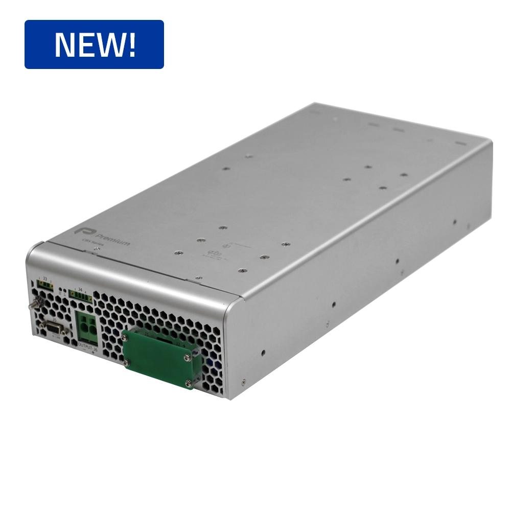
CBS-10K Three-Phase Resonant Unit
10 kW peak power isolated DC/DC platform with multi-phase LLC topology. Designed for ultra-wide input battery ranges (24 V to 110 V DC), yielding 97.8% efficiency under EN 50155 rolling stock stress tests.
6400 VA catenary-fed resonant inverter generating clean 3-phase sine wave output for rolling-stock HVAC, auxiliary power networks, and traction cooling pumps with active current sharing.
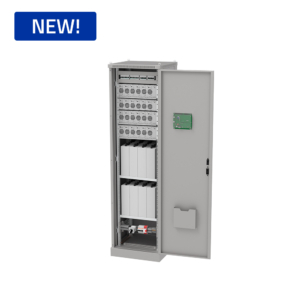
High-frequency modular rectifier rack capable of scaling to 72 kW. Employs 3-phase resonant front-ends with N+1 active redundancy for utility substations, data centers, and battery storage plants.
Accelerate your prototype cycle with over 260 standard power conversion products. Pre-qualified against strict electromagnetic, thermal, and mechanical shock norms, our building blocks allow engineering teams to validate specs in days.
Wide DC input windows: 24 V, 48 V, 72 V, 110 V, 750 V, 1500 V DC
Standard 19-inch rack, sub-floor chassis, or DIN rail form factors
Internal conformal coating options for humid/saline environments
Complete type-test reporting & 3D models available immediately
When off-the-shelf components cannot satisfy harsh environmental or structural footprints, our R&D team custom-engineers a dedicated Three-Phase Resonant Converter tailored to your exact mechanical envelope and electrical profile.
Custom planar magnetic matrix design and resonant tank tuning
Natural convection, liquid cooling plate, or forced air integration
Custom functional safety (SIL-2/SIL-3) & fault-tolerant control loops
Full First Article Inspection (FAI) and 20+ year life cycle guarantee
4. Future Procurement and Industry Growth Trends for Resonant Converters (2025–2035)
Global procurement specialists and technical directors face shifting supply chain dynamics, tightening environmental regulations, and escalating power density demands. Understanding the technology vectors driving Three-Phase Resonant Converters is vital for maintaining long-term competitive advantages and avoiding rapid asset obsolescence.
4.1 The Silicon Carbide (SiC) and Gallium Nitride (GaN) Transition
The convergence of Wide Bandgap (WBG) semiconductors—specifically 1200V Silicon Carbide (SiC) MOSFETs—with three-phase resonant topologies is redefining high-power conversion efficiency standards. SiC devices exhibit negligible output capacitance variation and superior breakdown field strength compared to legacy silicon switches. When paired with three-phase LLC soft-switching tanks, SiC-based resonant converters achieve full-load conversion efficiencies surpassing **98.5%**, while reducing heat sink thermal resistance requirements by half.
4.2 Expansion of DC Microgrids and High-Voltage DC Distribution
Modern industrial facilities, hydrogen electrolyzer plants, and green data centers are rapidly transitioning from legacy AC distribution grids to centralized high-voltage DC (HVDC) microgrids operating at 750V DC to 1500V DC. Three-Phase Resonant Converters serve as the cornerstone bridging high-voltage DC distribution to localized low-voltage equipment networks. Their inherent galvanic isolation, high dielectric strength, and bidirectional energy flow capabilities align perfectly with continuous 24/7 industrial production cycles.
4.3 Smart Predictive Maintenance via IoT Telemetry Integration
Industrial procurement is shifting from reactive replacement models toward proactive life-cycle management. Modern three-phase resonant converters feature digital DSP control cores that monitor phase balance, resonant tank frequency drift, planar core temperature gradients, and electrolyte capacitor degradation. By streaming telemetry via CANopen, Modbus, or IoT gateways, maintenance teams predict component wear years in advance, eliminating unscheduled downtime in critical railway grids and power substations.
Target Application Sectors
5. Mission-Critical Industrial Applications
Every industrial sector enforces unique safety, environmental, and normative frameworks. Premium PSU's three-phase resonant converter platforms are qualified to meet or exceed strict global standards:
Rail & Rolling Stock
On-board catenary inverters and battery chargers built to EN 50155, EN 45545-2 (HL3), and EN 61373 shock/vibration standards.
At Premium PSU, we believe reliability is calculated and engineered from the first schematic capture—never left to post-production testing. Our 40-year track record in Barcelona ensures that every three-phase resonant converter survives harsh real-world stress profiles for decades.
Rigorous Stress & Derating Analysis: All electrical components operate within strict thermal and voltage stress budgets (MIL-HDBK-217F & Telcordia SR-332 standards).
Advanced Thermal FEA & Magnetic Modeling: Pre-prototype finite element analysis (FEA) optimizes heat dissipation paths and planar transformer winding interleaving.
In-House ISO 17025 Compliant Test Lab: Full-spectrum EMC chambers, climatic temperature cabinets, and electrodynamic vibration tables accelerate qualification loops.
20+ Year Obsolescence Management: Long-term active bill-of-materials (BOM) tracking, component PCN notifications, and direct form-fit-function replacement guarantees for long-lifecycle projects.
Addressing core technical questions from global procurement leads, system integrators, and electrical engineering teams.
1. What is a Three-Phase Resonant Converter and why is it superior for high-power industrial applications?
A Three-Phase Resonant Converter combines three interleaved resonant inverter legs phase-shifted by 120 degrees operating into a shared dynamic transformer and rectifier matrix. Unlike conventional single-phase resonant converters, the three-phase topology achieves dynamic ripple cancellation on both input and output DC buses. This reduces peak inductor currents, cuts filter capacitance requirements by up to 80%, distributes thermal dissipation across six switching elements, and delivers smooth, low-EMI power conversion above 5 kW up to 72 kW.
2. How does soft-switching (ZVS/ZCS) increase conversion efficiency and system lifespan?
Soft-switching mechanisms—Zero-Voltage Switching (ZVS) at turn-on and Zero-Current Switching (ZCS) at turn-off—eliminate high-frequency switching power losses and turn-off voltage spikes. By ensuring switches transition only when voltage or current passes through zero, thermal stress on switching semiconductors (MOSFETs/IGBTs) is dramatically reduced. This leads to efficiency figures exceeding 97.5%, lower operating temperatures, and extended Mean Time Between Failures (MTBF) under continuous 24/7 industrial operation.
3. Why are planar transformers utilized instead of standard wire-wound magnetics?
Planar transformers utilize precision multi-layer printed circuit boards (PCBs) stacked within flat ferrite cores. This architecture provides exact control over leakage inductance ($\pm 1.5\%$), which is essential for maintaining matched resonant tank frequencies in multi-phase topologies. Additionally, planar magnetics offer low profile heights, superior heat dissipation directly into aluminum cold plates, and immunity to shock and vibration compliant with EN 61373 railway standards.
4. What standards and safety certifications apply to Premium PSU’s power systems?
Depending on target application sectors, our power conversion platforms are engineered and certified to EN 50155 (railway electronic equipment), EN 50121-3-2 (EMC compliance for rolling stock), EN 45545-2 (fire and smoke safety HL3), EN 61373 (shock and vibration), IEC 61010-1 (industrial safety), IEC 62368-1 (information technology and communication equipment), and CE/UL compliance frameworks.
5. What is the typical NRE and lead-time requirement for a custom three-phase resonant project?
A custom engineering program typically spans 16 to 28 weeks from detailed technical specification lock to delivered certified prototypes. By leveraging Premium PSU's pre-qualified building blocks—including modular digital DSP controller boards, planar core geometries, and proven soft-switching drive circuits—both NRE expenditure and prototype delivery times are reduced significantly.
6. How does Premium PSU handle component obsolescence for 20+ year industrial cycles?
We operate an active lifecycle management strategy designed specifically for long-lifecycle markets like railway, grid energy, and defense. We perform continuous BOM monitoring, provide early Product Change Notifications (PCNs), execute last-time-buys (LTB) for critical silicon, and offer guaranteed form-fit-function redesign services to keep installed fleets operational for decades.
Consult directly with a Senior Power Electronics Engineer
Submit your electrical requirements—input voltage range, output power, ambient thermal constraints, and compliance targets. Our Barcelona R&D engineering group will evaluate the optimal standard platform or custom path within 24 business hours.