
Choosing Railway DC/DC Converters is not simply a matter of matching voltage ratings. A converter sits between unstable onboard power and sensitive equipment. It must survive vibration, heat, electrical noise, and sudden load changes. A poor choice may look efficient on paper, yet fail inside a crowded traction cabinet.
Professor John G. Kassakian, a respected power-electronics authority, describes the field clearly: “Power electronics is the technology of controlling electrical energy.” That principle matters in railway applications. Engineers must examine input voltage range, output regulation, isolation, efficiency, thermal performance, and protection functions. They should also check compliance with EN 50155, EN 45545-2, IEC 61373, and relevant EMC requirements. Standards are not decoration.
Look closely at the real installation. Measure cabinet temperature near the converter. Consider whether airflow is restricted by filters, wiring, or neighboring equipment. A 300-watt unit may perform differently in a clean laboratory and a vibrating underfloor compartment. That difference is easy to underestimate.
Reliability comes first.
The selection process should include transient testing, overload behavior, short-circuit protection, service life, and supplier support. Redundant configurations may improve availability, but they also add cost, wiring, and new failure points. This is where design judgment matters. There is no universally perfect converter.
A careful comparison should evaluate lifetime value, not only purchase price. Datasheets rarely reveal every practical weakness. Field experience, transparent test reports, traceable components, and realistic derating calculations provide stronger evidence. The final choice should fit the train, the route, and the maintenance strategy—not merely the specification sheet.
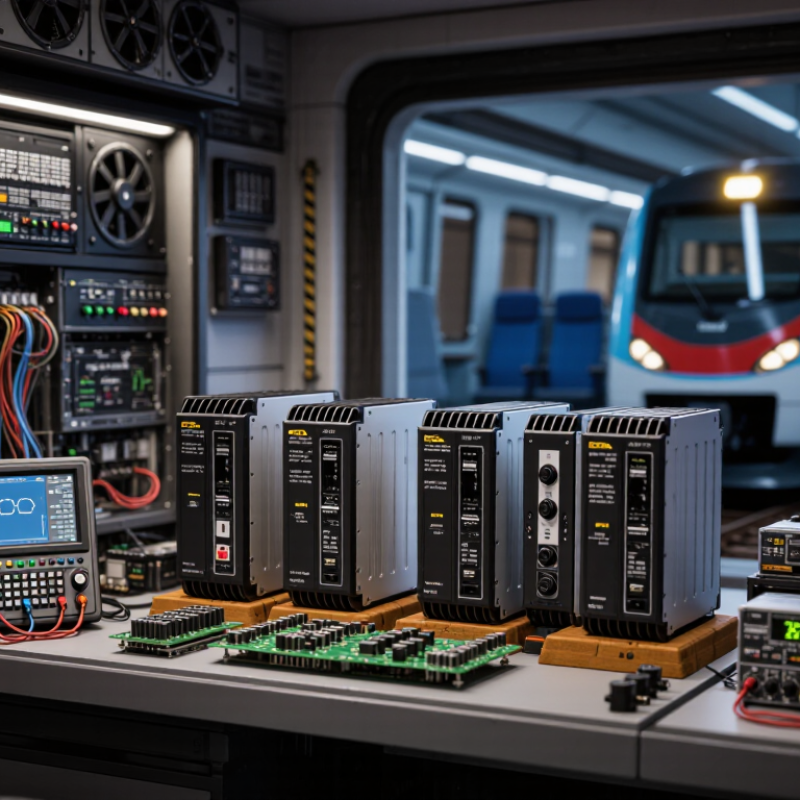
How to Choose Railway DC-DC Converters?
Railway DC-DC converters adapt unstable onboard power for sensitive electrical systems. They commonly supply signaling units, train control equipment, lighting, communication devices, and passenger information displays. Their main functions include voltage regulation, electrical isolation, filtering, and protection against overloads or short circuits.
Start with the railway battery or auxiliary bus voltage range. A converter must tolerate startup surges, voltage dips, and brief interruptions without resetting connected equipment. Check the required output voltage, continuous load, peak load, and isolation rating. Efficiency matters, but the printed figure can mislead. Heat losses still accumulate inside a sealed cabinet. Allow practical derating for high temperatures, dust, and restricted airflow.
Rail vehicles also produce vibration, shock, electromagnetic noise, and rapid temperature changes. Choose a converter tested for these conditions and review relevant railway requirements, such as EN 50155, EN 50124-1, and EN 45545 where applicable. Confirm EMC performance with the complete system, not only the converter on a laboratory bench. A quiet module may behave differently beside traction equipment.
Look closely at installation details. DIN-rail mounting, forced cooling, cable length, and connector locking can affect reliability. Include surge protection and remote monitoring when maintenance access is difficult. No selection is perfect. A spreadsheet may overlook a five-second voltage interruption in a tunnel. Test the converter with realistic loads, wiring, and cabinet temperatures before approving the design.
| Selection Dimension | Typical Railway Requirement | Why It Matters | Recommended Evaluation Point |
|---|---|---|---|
| Input Voltage | Common nominal systems include 24 V, 37.5 V, 72 V, 96 V and 110 V DC. | Railway batteries and auxiliary supplies can experience wide voltage variation during starting, charging and transient events. | Confirm the converter's continuous input range, start-up voltage, reverse-polarity protection and transient withstand capability. |
| Output Voltage | Typical outputs are 5 V, 12 V, 15 V, 24 V and 48 V DC, depending on the connected equipment. | Stable output voltage is required by control electronics, communication equipment, sensors, displays and monitoring systems. | Match the rated output voltage and allowable tolerance to the load manufacturer's specifications. |
| Output Power | Small control loads may require less than 50 W; communication, monitoring or auxiliary loads may require 100 W to several hundred watts. | Insufficient power can cause voltage sag, overheating or repeated shutdowns, especially during equipment start-up. | Calculate continuous and peak demand, then include a practical design margin of about 20% to 30% where operating conditions permit. |
| Electrical Isolation | Galvanically isolated input and output are commonly preferred for safety-critical, control and communication circuits. | Isolation helps prevent ground loops, limits fault propagation and separates noisy power circuits from sensitive electronics. | Check isolation voltage, insulation resistance, creepage and clearance distances, and the required safety architecture. |
| Efficiency | Modern railway-grade converters commonly achieve approximately 85% to 95% efficiency, depending on power and operating point. | Higher efficiency reduces battery drain, enclosure temperature and cooling requirements. | Review efficiency curves at minimum, nominal and maximum input voltage and at the actual expected load. |
| Thermal Performance | Operation may be required across a broad ambient temperature range, often around −40°C to +70°C, with derating at higher temperatures. | Rail vehicles may place converters in underfloor, rooftop, equipment-cabinet or engine-compartment locations with limited airflow. | Check the rated ambient range, natural or forced cooling method, thermal derating curve and maximum case temperature. |
| EMC and Noise | Low conducted and radiated emissions are important in traction, signaling, control, radio and passenger-information systems. | Switching noise can interfere with train communication, measurement systems, signaling circuits and other sensitive equipment. | Review conducted and radiated emission test results, filtering design, switching frequency and installation grounding requirements. |
| Protection Functions | Overvoltage, undervoltage, overcurrent, short-circuit, overload and overtemperature protection are widely expected. | Protection prevents damage during wiring faults, abnormal loads, blocked ventilation and unstable auxiliary power conditions. | Determine whether protection is foldback, hiccup, latch-off or auto-recovery, and verify coordination with upstream fuses or breakers. |
| Mechanical Design | Compact, rugged enclosures with secure mounting and suitable terminal or connector arrangements are generally required. | Space, vibration, shock, dust and moisture constraints vary between onboard cabinets, underfloor equipment and trackside installations. | Confirm dimensions, mounting orientation, ingress protection, connector retention and service-access requirements. |
| Railway Compliance | Applications may require compliance with railway standards covering electronics, EMC, shock, vibration, fire behavior and environmental conditions. | Compliance supports system safety, electromagnetic compatibility and reliable operation throughout the vehicle or infrastructure life cycle. | Request current test reports and declarations related to EN 50155, EN 50121-3-2, EN 61373 and EN 45545-2, as applicable to the installation. |
| Reliability and Service Life | Long service life, predictable maintenance and stable performance under continuous duty are important for rolling stock and infrastructure. | Unexpected converter failure can interrupt vehicle availability, passenger services or signaling and monitoring functions. | Evaluate component quality, MTBF information, burn-in testing, warranty terms, repairability and long-term product availability. |
Choosing a railway DC-DC converter starts with the vehicle’s real power profile, not its nominal voltage. Railway systems commonly use 24, 48, 72, 96, or 110 VDC auxiliary supplies, as listed in EN 50155. Measure the input during engine start, braking, battery charging, and pantograph changeover. A converter rated only for laboratory voltage may fail during these sharp transitions.
Load behavior matters equally. Record continuous demand, inrush current, standby consumption, and short overload duration for radios, control units, lighting, and passenger-information equipment. EN 50155 addresses railway temperature, humidity, voltage variation, and electromagnetic compatibility. IEC 61373 classifies vibration by mounting location, including body, bogie, and axle positions. The UIC Railway Handbook 2023 also highlights increasing onboard digital equipment, which raises the need for cleaner and more stable auxiliary power. More electronics means less tolerance for ripple.
Tips: Build a 24-hour load profile from measured data. Keep at least 20% headroom, then test it under worst-case temperature and vibration. Check galvanic isolation, creepage distance, cooling airflow, and conducted emissions. A practical mistake is sizing from average watts. Peak current often decides the converter. I have seen installation teams overlook cable losses between batteries and cabinets; that small error can create a large voltage drop. Recheck it. Use EN 50155 and IEC 61373 test evidence when comparing suppliers.
Choosing a railway DC-DC converter begins with the vehicle’s electrical map, not a catalog headline. Measure the input range during battery sag, regenerative peaks, and cold starts. A converter rated for nominal voltage may fail at the edges. Check isolation voltage, creepage distance, and insulation monitoring requirements. In practice, measure voltage at the converter terminals. Cable drops can exceed early estimates. Small details matter.
Topology affects more than efficiency. A buck stage suits step-down service, while a boost stage supports higher output voltage. For isolated systems, full-bridge and resonant designs can improve voltage conversion and safety. However, each topology brings different switching losses, control behavior, and electromagnetic interference risks. Examine ripple current and transient response near traction loads. Keep the oscilloscope nearby. Under light loads, efficiency may fall sharply. Datasheet graphs often show ideal conditions, not a vibrating cabinet in winter.
Compare continuous power, overload duration, short-circuit protection, and thermal derating. Do not trust one number. A 2 kW rating means little without its ambient temperature and cooling method. Review airflow paths, enclosure protection, vibration resistance, and connector locking strength. Test the converter with a real load profile, including startup and sudden braking events. A design can look correct and still be poorly verified. I would also repeat temperature testing, because one successful run may hide a weak margin. Reliability is built from measured behavior, not attractive specifications.
Choosing a railway DC-DC converter starts with evidence, not nominal input and output voltage. UNIFE’s World Rail Market Study 2024 forecasts roughly 3% annual growth in rail supply demand through 2027. That pressure can reward low-cost choices. It should not weaken verification. ERA’s 2024 Railway Safety Performance Report recorded 1,567 significant railway accidents in the European Union during 2022. Request test records, failure data, and traceable production controls. Check EN 50155 for temperature, supply interruptions, EMC, and electronic equipment qualification. Apply EN 50126, EN 50128, and EN 50129 when the converter supports safety-related functions.
Reliability is more than a long warranty. Calculate derating at maximum load, cabinet temperature, and degraded cooling. A converter operating at 80% load may behave differently inside a sealed underfloor enclosure. Use MTBF carefully; field returns and repair time often reveal more. IEC 61373 vibration testing matters near traction equipment. EN 45545-2 addresses fire behavior, while IEC 60068 methods assess humidity, shock, and thermal cycling. Ask whether tests used the actual mounting bracket and cable length. Laboratory confidence can be misleading.
Environmental resistance needs route-specific evidence. Salt mist, ballast dust, condensation, and rapid temperature changes may occur during one service day. Review ingress protection, conformal coating, connector sealing, and insulation monitoring. Measure ripple, transient response, and isolation resistance under hot and cold conditions. The converter should tolerate brownouts without damaging downstream controls. I would challenge any report showing only clean-room performance. Independent witness testing adds credibility, but fleet feedback remains essential.
Choosing a railway DC-DC converter starts with the actual electrical environment, not the catalog headline.
Record the nominal, minimum, and maximum input voltage. Include battery charging voltage and short transients. A 72 V system may experience far more than 72 V during switching events. Check the required output voltage, current, peak load, and startup sequence. Leave practical headroom.
Isolation is equally important. Verify insulation voltage, creepage, clearance, and leakage current against the system architecture. Then examine efficiency across the real load range, not only at full load. A converter operating beside braking equipment may face vibration, dust, and restricted cooling. Review thermal derating curves carefully. A small enclosure can become surprisingly hot. I have seen acceptable laboratory results fail after cabinet temperatures rose above 60°C.
Verification should combine documents with physical testing. Confirm compliance with relevant railway requirements for environmental performance, EMC, fire safety, and electrical insulation. Ask for test conditions, not just certificate titles.
Test input dips, surges, reverse polarity protection, output short circuits, and repeated power cycling. Measure output ripple with suitable probes and realistic cable lengths. Check startup behavior with the final load attached.
A spreadsheet can still lie. Compare measured temperatures at terminals, capacitors, and switching components. Record every abnormal noise, delay, or restart. Those details often reveal weaknesses before installation. Independent review is valuable, especially when the converter supports signaling, control, or passenger safety functions.
It changes unstable onboard DC power into a controlled voltage. It supports signaling, control equipment, lighting, communication, and passenger displays. It also provides isolation, filtering, and overload protection.
Check the nominal, minimum, and maximum battery or auxiliary-bus voltage. Include charging voltage, startup surges, voltage dips, and brief interruptions. A 72 V system may exceed 72 V during switching.
Measure continuous demand, startup current, standby use, and short overload periods. Keep practical headroom, often at least 20 percent. Average watts can mislead. Peak current often decides the converter.
Heat accumulates inside sealed cabinets, even when efficiency looks high. Review derating curves at high temperatures. Measure temperatures near terminals, capacitors, and switching components.Small cabinets get hot.
Railway vehicles create vibration, shock, electromagnetic noise, dust, and rapid temperature changes. Mounting location can change the vibration level. A converter near traction equipment may behave differently from one tested alone.
Check mounting rails, airflow, cable length, connector locking, and cabinet space. Cable losses can create a surprising voltage drop between batteries and equipment. I would recheck this detail.
Confirm galvanic isolation, insulation voltage, creepage distance, and clearance. Test surge response, reverse-polarity protection, overload protection, and output short-circuit behavior. Remote monitoring helps when maintenance access is difficult.
Test it with realistic loads, final wiring, and expected cabinet temperatures. Include voltage dips, surges, repeated power cycles, and startup with the full load connected. Measure ripple using suitable probes. Record every restart, delay, abnormal sound, and temperature rise. A spreadsheet can still lie.
Choosing the right Railway DC/DC Converters is essential for ensuring stable, efficient, and safe power distribution across railway systems. The selection process begins by understanding the converter’s role, such as adapting battery, auxiliary, signaling, control, or communication power to the required voltage levels. It is also important to evaluate input voltage range, output power, load characteristics, efficiency, isolation, transient response, and compatibility with the railway’s operating conditions.
A reliable choice should match the system’s topology and electrical ratings while providing strong protection against overloads, short circuits, voltage fluctuations, vibration, dust, humidity, and temperature changes. Safety, service life, electromagnetic compatibility, and applicable railway standards must also be considered. Before final approval, engineers should verify the converter through technical documentation, laboratory testing, and, where possible, operation under realistic conditions. A careful comparison of performance, environmental resistance, maintenance needs, and long-term reliability will help ensure that the selected solution supports dependable railway operation.